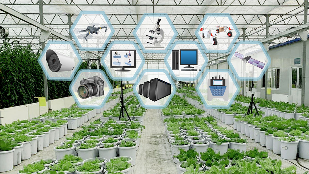
Phenomics involving in multidisciplinary technologies is the cutting-edge method to systematically study the phenotypes. Our current experimental data acquisition system was built in the greenhouse of BAAFS, providing a planar scanning motion mechanism. By using sensor, industrial control and phenotypic analysis technology, RGB image, thermal infrared image, laser point cloud, spectrum and environmental sensor were efficiently integrated and applied to our phenotypic acquisition platform and phenotypic analysis system for lettuce. The collected information includes images of top view, shapes of leaves, 3D structure of whole plants, etc. More traits and relative information will be released in the near future.

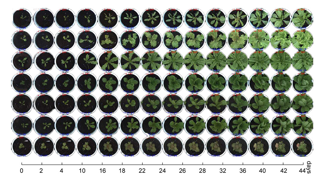
The left figure shows an example of high-throughput phenomic study from our LBG group. Lettuce plants were transplanted into large pots of the greenhouse after 30 day germination and seedling in small pots. The diameter and height of the pots were 32 cm and 34 cm respectively. The lettuce phenotypic data were collected at 16:00 p.m every other day, and datasets of over 2000 plants from 500 lettuce varieties were thus captured at eight time points during vegetative growth. At that time, the photo-period and photosynthesis in the greenhouse was basically the same for all lettuce varieties. In this study, image datasets at 44 days of lettuce growth were used to evaluate the static and dynamic traits (growth and accumulation rates were calculated based on the changing curves of static traits at eight growth points).

The high-throughput phenotyping platform was built in a terraced greenhouse at the Beijing Academy of Agriculture and Forestry Sciences (BAAFS). The greenhouse structure was the conventional steeple terraced with a height of 6 m, a ceiling height of 6.5 m, a single span of 10.5 m, and a length of 45 m. The design of the phenotyping platform is shown in Fig. 1A. Based on the ten load-bearing columns in the greenhouse, the north–south double-track beam (X) was installed at the height of 4.5 m above the ground, with a length of 40 m for each column, including two sets of synchronous motors, high-precision racks, synchronous belts, limit switches, and other components. The east–west beam frame (Y) was installed on the double-track beam and can control the overall motion in the X-axis direction. The beam frame also adopts the double-track beam as the basic structure, with an interval of 0.8 m. The rail trolley was mounted on it and can move stably in the Y-axis direction, including a set of synchronous motors, high-precision rack, synchronous belt limit switches, and other components.
The platform railcar could move in the east–west direction (Y-axis). The lower side of the railcar was equipped with a 5-stage lifting device, the bottom layer with a rotating platform, and an imaging box was installed under the rotating platform. The lifting device adopted a hierarchically nested frame structure with a height of 0.8 m. Screw rods were used to fix the frames, and independent motors were used to control the inner edge to rise and fall. The five-layer structure contained four sets of frame telescopic devices, and each group consisted of two sets of screw rods and motors. Therefore, the lifting device consisted of 8 motors and adopts the resistance lifting method to increase and decrease gradually until the appropriate height. The fully rising state was 3.8 m above the ground, while the fully reduced form was 1.4 m from the ground. A circular rotating table of diameter 0.4 m were installed at the bottom of the innermost frame of the telescopic device. An imaging box with 0.8 × 0.8 × 0.8 m size was fixed on the rotating table that could rotate up to 360 degrees under the control of a stepper motor. Therefore, the imaging box had four degrees of freedom (X-Y-Z-R), which could adapt to the data acquired from different imaging heights and shooting angles.
The phenotyping platform adopted three sets of automatic systems to control the motion of the imaging unit in the greenhouse, namely, the plane track control system (X-Y), the lifting control system (Z), and the rotation system (R). The X-Y track control system had four sets of motors and eight limit switches (Fig. 1A). Three sets of automatic control systems could enable movement of the imaging unit at four degrees of freedom (DOFs), thus met the necessity of evaluating different types of traits. Also, the control imaging unit of the plane track control system could collect data in the same X-Y plane. The lift control system determined the distance from the sensor to plants, thus met the requirements of the different growth stages and image resolution (Fig. 1B). Lifting device combined with an imaging unit was utilized to control imaging height, and the rotation system determined the imaging orientation Fig. 1C). When the data acquisition system was activated, the platform could automatically capture images at the specified time interval and stored it in the JPG image format.